"In traditional design processes, the design information is usually transferred and handled in the form of text-based documents, which are difficult to understand and subject to interpretation bias. Engineers create embedded code and data manually from text-based documents, leading to a time consuming and error-prone process. There is also little scope to ensure that changes are implemented correctly or not.
The market demands embedded products that are highly customizable, life-long maintainable, recyclable and that can be disassembled, as well as which no longer follow any traditional design process models.
For embedded control and algorithm designers, the focus is on modeling, which has always been an essential part of the design process. The model-based design is a prominent change in embedded system development. In this context, when MBD is used effectively, it provides a single design platform to optimize overall system design. It helps embedded software developers to understand the difference between simulator and software development tool in order to create simulation models and check whether algorithms will work before the embedded code is written. Through virtual prototyping, system engineers can easily see whether the whole system (mechanical, electrical, and embedded software) will work as intended, even before the hardware is manufactured and available for testing." [1].
What is Simulink?
Simulink® is a multi-domain modeling and simulation environment for engineers and scientists who design controls, wireless, and other dynamic systems (Figure 1). Its primary interface is a graphical editor for modeling all components of a system and a customizable set of pre-built blocks for modeling algorithms and physical systems.
Building a Simulink model for a system consists of selecting the appropriate blocks and connecting them together in a way that enables the desired functionality. Adding blocks happens by dragging and dropping them from the Simulink library to the desired location on the model building stage. Furthermore, a connected set of blocks can be encapsulated into a component that provides a layer of abstraction that facilitates creating complex models.
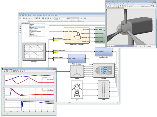 Figure 1: Simulink
Qt Design Studio 1.6
The new Qt Design Studio 1.6 release comes with built-in Simulink communication capabilities. A simulation model created using Simulink can interact with a QML application developed using Qt Design Studio. Data can flow in both directions between the 2 parties. This allows complete separation between the data (Simulink model) and its visual representation (QML app). This new feature is available for our commercial users and is still experimental. As of now, only Windows is supported and Simulink Qt blockset works with MATLAB version 2019b. In the next release we will support all MATLAB versions starting from version 2015b up to the latest. Also, we will improve the usability and features based on user feedback.
The power of using Simulink with Qt Design Studio comes from the neat separation of concerns. An engineer can work on building the simulation model in Simulink while a visual artist is building the UI in Qt Design Studio without any overlapping work between them. The integration between the Simulink model and the QML application then takes place via few simple steps on each side as discussed in detail further below.
Simulink Qt blockset
In order to connect a Simulink model to a Qt/Qt Design Studio app, Simulink Qt blockset is required. The Qt blockset installer adds the Simulink blocks needed to establish connectivity to a QML application. The installer supports MATLAB version R2019b only as of now. After installation, “SLQTLibrary” blockset will be added to the Simulink blocks library. The blocks allow sending and receiving of Property, Qt Signal, and Slot, updates with a QML app. The Qt blockset consists of 5 Qt blocks (Figure 2) that are intuitive to use. There is one block for sending and one for receiving data with a QML based application.
 Figure 2: Simulink Qt blockset
Simulink – Qt Design Studio integration
Integrating a Simulink model with a QML application is a simple process. Let’s look at the Simulink side first. Figure 3 demonstrates a typical setup for connecting a Simulink model (Subsystem in Figure 3) with a QML application. First, a Simulink-Qt CLIENT block is needed. It takes an IP address of the server for the client block (QML application’s machine IP address), and a port as input. For simulations where the Simulink model and the QML application are on the same machine, IP address “127.0.0.1” and any available port should be used. A Qt/QML SEND block is used for each property that needs to be sent from Simulink side to QML side. Likewise, a Qt/QML RECEIVE block is used for each property that needs to be received from QML side to Simulink side. Each send and receive block must be assigned a property name that corresponds to the name of the property or slot in the QML application.
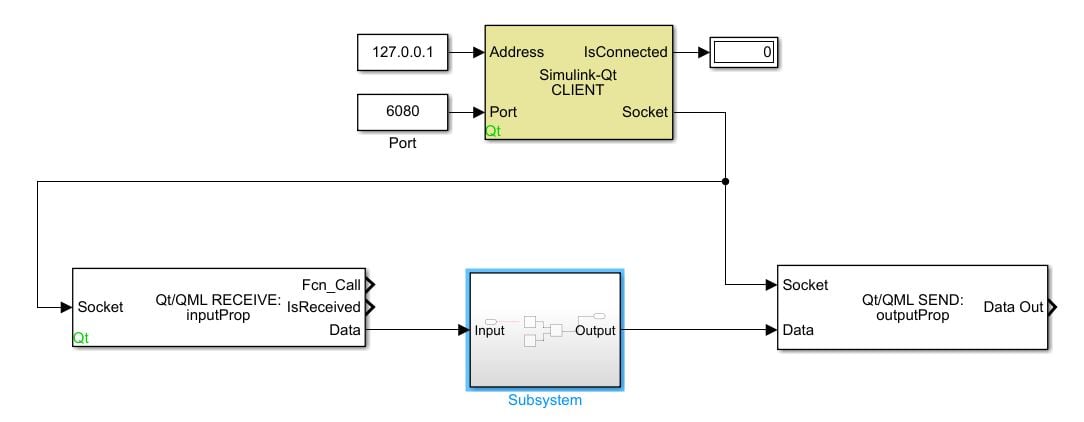 Figure 3: Typical setup on a Simulink Model to send and receive data with a QML application
On Qt Design Studio side, the setup consists of two simple steps:
- Adding the SimulinkConnector QML import via QML imports window (Figure 4). If you need to change the IP and/or port, you need to select the SLConnector in Navigator and set the IP and/or port in the properties panel. Since SLConnector is a non-visual item, you need to first click the filter icon on Navigator's header and untick "Show only visible items". After that you can see the SLConnector in the Navigator's hierarchy.
- Creating custom properties on the root of the main QML file that matches the send and receive blocks on the Simulink side (figure 5).
|
|
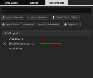
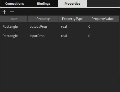 Figure 5: QML properties on the root object
Now The Qt application is ready to send and receive data with the simulink model. All that is remaining is to bind the created root properties to the desired QML objects properties.
What about testing on device?
Simulink can export a model as C/C++ code using MATLAB's Embedded Coder. Embedded coder generates fast and optimized code that is efficient for running on embedded processors. The generated code can be integrated both with a Qt Quick based HMI as well as a Qt Quick Ultralite based HMI.
Give it a try!
You need Qt Design Studio 1.6 commercial version and MATLAB 2019b with Simulink to setup the integration. If you have a commercial license, you should be able to access the latest version from your Qt Account or online installer. The commercial standalone Qt Design Studio 1.6 is available on our online shop. MATLAB and Simulink are found on their official website. The Simulink Qt blockset installer can be found in this repository (QtBlocksetPSP-R2019b_v2.1.3_win64-Install.exe).
For questions, or inquiries please use the contact us page.
Comprehensive documentation for the Simulink integration with Qt Design Studio is coming soon to the Qt Design Studio Manual.
[1] https://www.einfochips.com/blog/why-is-model-based-design-important-in-embedded-systems/