Sep 5, 2022
Introduction
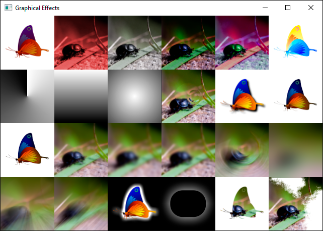
Qt Graphical Effects was one of the modules left out from the original Qt 6.0 release, unfortunately without a direct replacement at the time. There was a port available as source, but it wasn't built or included in the official releases.
One of the reasons was that not all effects were compatible with the Qt 6 approach of precompiling shader code: Some shaders in Qt Graphical Effects are generated at run-time from the properties, to enable pregenerating tables such as Gaussian weights. With the introduction of RHI in Qt 6, we now compile shader code at build time. This can give considerable improvements for startup times and frame rate during loading, but the trade-off is that it somewhat restricts our ability to generate code on the fly.
And, in addition, we had seen over the years that there was a fundamental drawback in how the graphical effects were designed. Chaining effects requires an additional draw call, an additional set of shader passes and an additional offscreen buffer for each effect you add. This causes the chained effect to be both slower and more memory hungry than it needs to be. The end result was that users would often implement custom effects instead, in order to optimize their applications. We thought we could do better, and therefore we did not officially include Qt Graphical Effects in the first releases of Qt 6.
However, Qt Graphical Effects is undeniably a useful module, and many users were disappointed by its absence. After plenty of helpful feedback, we added the module back as part of the Qt 5 Compat namespace: In Qt 6.2 we added back all effects except the ones that required run-time generation of code, and now, in Qt 6.4, the remaining types have been reinstated. The module is now fully compatible with the one in Qt 5.
We are also working on what we think is a superior solution: The Qt Quick Effect Maker, as demonstrated in the Qt Contributor Summit 2022. When it is ready, this will allow you to customize your effects in a visual tool. You will hear more about this later.
Custom Shaders
While we were discussing this topic internally, I realized that we may not have bragged enough about the custom shader effect capabilities in Qt Quick lately. Qt Graphical Effects and Qt Quick Effect Maker are great utilities of convenience, but with just regular Qt Quick you already have extremely powerful graphics tools at your fingertips.
It does require writing shader code, which can be daunting if you've never done it before, but once you get past the boiler plates and declaration syntax, it should actually be quite familiar to anyone who is used to programming in C++.
In this blog, I will implement a custom effect which applies both a Gaussian blur and a colorization filter in a single pass, without the overhead associated with chaining Qt Graphical Effects together. I will try to explain the details as much as possible, so hopefully it can be a starting point for readers to experiment and play.
As a very basic introduction: Shaders are programs that are run on the GPU itself, as part of the rendering pipeline. The rendering pipeline has many different phases, and many can be customized using a shader program. In this blog, however, we will only focus on what is called the "fragment shader". For our purposes we can think of a fragment as a pixel, and I will use the terms interchangeably. The fragment shader is run for every pixel in the output, so every time a color is drawn into the scene, it is actually some fragment shader calculating which color it should be.
Box Blur
We will start by writing a simple box blur.
The box blur algorithm works as follows: For each pixel in the output, center a square box of some configurable size (often called the kernel) on the corresponding pixel in the source and calculate the average of all the pixels in the box. This average becomes the output color.
Shader code
The shader code for a box blur effect can look as follows. Our input in this case could be any rectangular Qt Quick item. In the example project, the input is an image.
#version 440

layout(location = 0) in vec2 qt_TexCoord0;
layout(location = 0) out vec4 fragColor;

layout(std140, binding = 0) uniform buf {
    mat4 qt_Matrix;
    float qt_Opacity;
    vec2 pixelStep;
    int radius;
};
layout(binding = 1) uniform sampler2D src;

void main(void)
{
    vec3 sum = vec3(0.0, 0.0, 0.0);
    for (int x = -radius; x <= radius; ++x) {
        for (int y = -radius; y <= radius; ++y) {
            vec2 c = qt_TexCoord0 + vec2(x, y) * pixelStep;
            sum += texture(src, c).rgb;
        }
    }

    fragColor = vec4(sum / ((radius*2 + 1) * (radius*2 + 1)), 1.0) * qt_Opacity;
}
Lets go through this line by line to see what's going on:
#version 440The first line just gives the version of the shader language used, and can for our purposes always be 440. Qt will compile the shader code to different byte code representations for different target graphics APIs (or to GLSL in the case of OpenGL).
layout(location = 0) in vec2 qt_TexCoord0;The first input is the texture coordinates. The type is vec2, which means it is a vector of two components.
Behind the scenes, Qt Quick will split our source image into two triangles and pass these to the GPU for rendering. Then a vertex shader is executed (this is a shader phase that operates on the vertices rather than pixels) which calculates the texture coordinates at each vertex. The texture coordinate is the position in the source image which corresponds to the vertex. These values are interpolated for each pixel inside the triangles and then provided to the fragment shader, so that it knows exactly which pixel in the source corresponds to the current fragment it is rendering.
The default vertex shader in Qt Quick calculates normalized texture coordinates: qt_TexCoord0.x == 0 is at the left-most side of the input and qt_TexCoord0.x == 1 is at the right-most side.
The layout qualifier together with in gives the index of the varying parameter ("varying" refers to parameters that are potentially different for each pixel, interpolated from numbers calculated in the vertex shader.) Essentially we are saying that whatever the vertex shader has as its first output should be called "qt_TexCoord0" in the context of our fragment shader code, so it's important that the index matches what is predefined in Qt's default vertex shader. On OpenGL, it is also important that the name matches. This means that when targetting OpenGL and using the default vertex shader, this parameter must be named "qt_TexCoord0".
Unless you write a custom vertex shader, the first varying input parameter is always the texture coordinates, and this code can be left exactly like it is.
layout(location = 0) out vec4 fragColor;The main output is the color of the destination pixel, and we give this the name fragColor so that we can refer to it. The expected format of the output color is a vector with four components: (r, g, b, a) where each component is a normalized number between 0 and 1. If we were to set this to (1, 0, 0, 1) for instance, the output would always be fully saturated and fully opaque red.
This code should also remain the same for all your custom shaders.
layout(std140, binding = 0) uniform buf {
    mat4 qt_Matrix;
    float qt_Opacity;
    vec2 pixelStep;
    int radius;
};
In addition to the "varying" parameters, we also have "uniform" parameters. These are parameters that are set for the render pass as a whole, but remain the same for all pixels (and all vertices for that matter). As we will see later, Qt makes it very easy to pass uniform parameters to the shader effect.
The first two parameters are expected to be present in all shaders in Qt: The main MVP matrix and the opacity of the item based on its (and its ancestors') opacity in Qt Quick. The "pixelStep" and "radius" uniforms are added as specific to this shader effect.
You can append new uniforms to the end of this buffer, but you can't remove the matrix or opacity properties, nor change their order.
layout(binding = 1) uniform sampler2D src;All uniforms of primitive types can be bundled in the uniform buffer as shown above, but textures have to be bound individually. In our case, we have a single texture, representing the source image that we want to blur.
The main function is the entry point of the shader, and the rest of the code is what actually converts the input data into a color.
void main(void)
{
    vec3 sum = vec3(0.0, 0.0, 0.0);
    for (int x = -radius; x <= radius; ++x) {
        for (int y = -radius; y <= radius; ++y) {
            vec2 c = qt_TexCoord0 + vec2(x, y) * pixelStep;
            sum += texture(src, c).rgb;
        }
    }

    fragColor = vec4(sum / ((radius*2 + 1) * (radius*2 + 1)), 1.0) * qt_Opacity;
}
The code here sums up all pixels in the square kernel, using the built-in texture command to sample the input at specified locations.
There is one small obstacle though: Since the texture coordinates are normalized and we don't know the size of the input, we don't actually have any way of knowing the distance from a pixel to its neighbours (if the input is 10x10, then pixels are 0.1 apart in normalized coordinates, whereas if the input is 100x100 then pixels are 0.01 units apart.)
To hack around this problem, we supply the normalized size of a single pixel as a uniform called "pixelStep". In our QML code, we will pass (1/imageWidth, 1/imageHeight) for this parameter.
In the end we divide by the number of pixels in the sum, i.e. the area of the kernel, and thus get the average. We then assign this to our output parameter, fragColor.
CMake and QML code
For anyone used to developing Qt Quick applications, the project structure and code in the example should look familiar. One special thing to notice in the build script is the part that actually adds the shader to the project.
qt6_add_shaders(boxblurblog "shaders"
    BATCHABLE
    PRECOMPILE
    OPTIMIZED
    PREFIX
        "/"
    FILES
        "boxblur.frag"
)
This command causes the source code in "boxblur.frag" to be compiled into a .qsb file, which can later be loaded into Direct3D, Vulkan, Metal or OpenGL - whichever graphics backend happens to be active.
The shader is loaded using the ShaderEffect type in Qt Quick.
ShaderEffect {
    property var src: bug
    property int radius: 32
    property var pixelStep: Qt.vector2d(1/src.width, 1/src.height)
    anchors.left: bug.right
    anchors.right: parent.right
    anchors.top: bug.top
    anchors.bottom: bug.bottom
    fragmentShader: "boxblur.frag.qsb"
}
We are loading the .qsb file generated by the build system.
In addition we are defining properties for the uniforms in the shader. Qt will automatically match up QML properties to uniforms by looking at their names, so passing data to the shader is super-simple: Just make sure the types are also matching.
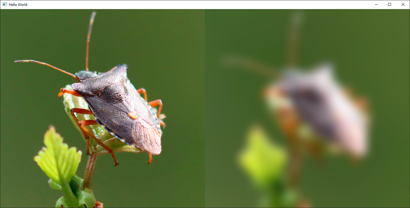
Note that in our case, "bug" is an Image component, but it could also be a ShaderEffectSource for passing in arbitrary Qt Quick items. We set the radius of the kernel to 32 and supply the normalized size of a pixel as mentioned earlier.

The result is blurred, but if you compare to actual optical blurring, it doesn't look quite right. The boxiness inherent in the algorithm is visible in the output as well. The reason for this is that all pixels in the kernel contribute an equal amount to the end result. In the real world, you would expect pixels closer to the output pixel to contribute more.
Gaussian Blur
This is what the Gaussian blur addresses: Instead of just doing a rough average of the pixels, the contribution of each pixel is weighted by a function of its distance to the center of the kernel. The function we use is the Gaussian function, which is a statistical function that describes normal distribution.
We change our fragment shader to implement a gaussian blur:
#version 440

layout(location = 0) in vec2 qt_TexCoord0;
layout(location = 0) out vec4 fragColor;

layout(std140, binding = 0) uniform buf {
    mat4 qt_Matrix;
    float qt_Opacity;
    vec2 pixelStep;
    int radius;
    float deviation;
};
layout(binding = 1) uniform sampler2D src;

#define PI 3.1415926538

float gaussianWeight(vec2 coords)
{
    float x2 = pow(coords.x, 2.0);
    float y2 = pow(coords.y, 2.0);
    float deviation2 = pow(deviation, 2.0);

    return (1.0 / (2.0 * PI * deviation2)) * exp(-(x2 + y2) / (2.0 * deviation2));
}

void main(void)
{
    vec3 sum = vec3(0.0, 0.0, 0.0);
    float gaussianSum = 0.0;
    for (int x = -radius; x <= radius; ++x) {
        for (int y = -radius; y <= radius; ++y) {
            vec2 c = qt_TexCoord0 + vec2(x, y) * pixelStep;
            float w = gaussianWeight(vec2(x, y));
            sum += texture(src, c).rgb * w;
            gaussianSum += w;
        }
    }

    fragColor = vec4(sum / gaussianSum, 1.0) * qt_Opacity;
}
We have now defined a new function in the shader which returns the Gaussian weight for a pixel which is at distance "coords" from the center of the kernel. We have also added a "deviation" uniform for extra customizability. Instead of calculating the mean of all values, we now multiply each sample with this Gaussian weight instead. Looking at the result, it's clear that the Gaussian blur gives much fewer artifacts and looks more like an optical blur.
It is worth noting that calculating the Gaussian weights in the fragment shader can be quite expensive. A more efficient approach would be to precalculate the weights for our chosen kernel size and then hardcode these into either the shader or the uniform input. This is why the Gaussian blur in Qt Graphical Effects is generating the shader source code at runtime based on the input values.
Replacing the contents of the gaussianWeight() function in the code with such hardcoded values would be a simple way of enhancing the code in this blog.
Colorize Effect
One of the great benefits of creating a custom shader is that you can now simply add additional effects on top with minimal overhead. To illustrate this, we will finish off by adding a colorize filter to the Gaussian blur shader.
To make it simple, I've copied some code from the Colorize filter in Qt Graphical Effects.
#version 440

layout(location = 0) in vec2 qt_TexCoord0;
layout(location = 0) out vec4 fragColor;

layout(std140, binding = 0) uniform buf {
    mat4 qt_Matrix;
    float qt_Opacity;
    vec2 pixelStep;
    int radius;
    float deviation;
    float hue;
    float saturation;
    float lightness;
};
layout(binding = 1) uniform sampler2D src;

#define PI 3.1415926538

float gaussianWeight(vec2 coords)
{
    float x2 = pow(coords.x, 2.0);
    float y2 = pow(coords.y, 2.0);
    float deviation2 = pow(deviation, 2.0);

    return (1.0 / (2.0 * PI * deviation2)) * exp(-(x2 + y2) / (2.0 * deviation2));
}

float RGBtoL(vec3 color)
{
    float cmin = min(color.r, min(color.g, color.b));
    float cmax = max(color.r, max(color.g, color.b));
    float l = (cmin + cmax) / 2.0;
    return l;
}

float hueToIntensity(float v1, float v2, float h)
{
    h = fract(h);
    if (h < 1.0 / 6.0)
        return v1 + (v2 - v1) * 6.0 * h;
    else if (h < 1.0 / 2.0)
        return v2;
    else if (h < 2.0 / 3.0)
        return v1 + (v2 - v1) * 6.0 * (2.0 / 3.0 - h);

    return v1;
}

vec3 HSLtoRGB(vec3 color)
{
    float h = color.x;
    float l = color.z;
    float s = color.y;

    if (s < 1.0 / 256.0)
        return vec3(l, l, l);

    float v1;
    float v2;
    if (l < 0.5)
        v2 = l * (1.0 + s);
    else
        v2 = (l + s) - (s * l);

    v1 = 2.0 * l - v2;

    float d = 1.0 / 3.0;
    float r = hueToIntensity(v1, v2, h + d);
    float g = hueToIntensity(v1, v2, h);
    float b = hueToIntensity(v1, v2, h - d);
    return vec3(r, g, b);
}


void main(void)
{
    vec3 sum = vec3(0.0, 0.0, 0.0);
    float gaussianSum = 0.0;
    for (int x = -radius; x <= radius; ++x) {
        for (int y = -radius; y <= radius; ++y) {
            vec2 c = qt_TexCoord0 + vec2(x, y) * pixelStep;
            float w = gaussianWeight(vec2(x, y));
            sum += texture(src, c).rgb * w;
            gaussianSum += w;
        }
    }

    float light = RGBtoL(sum / gaussianSum);
    float c = step(0.0, lightness);
    vec3 color = HSLtoRGB(vec3(hue, saturation, mix(light, c, abs(lightness))));
    fragColor = vec4(color, 1.0) * qt_Opacity;
}
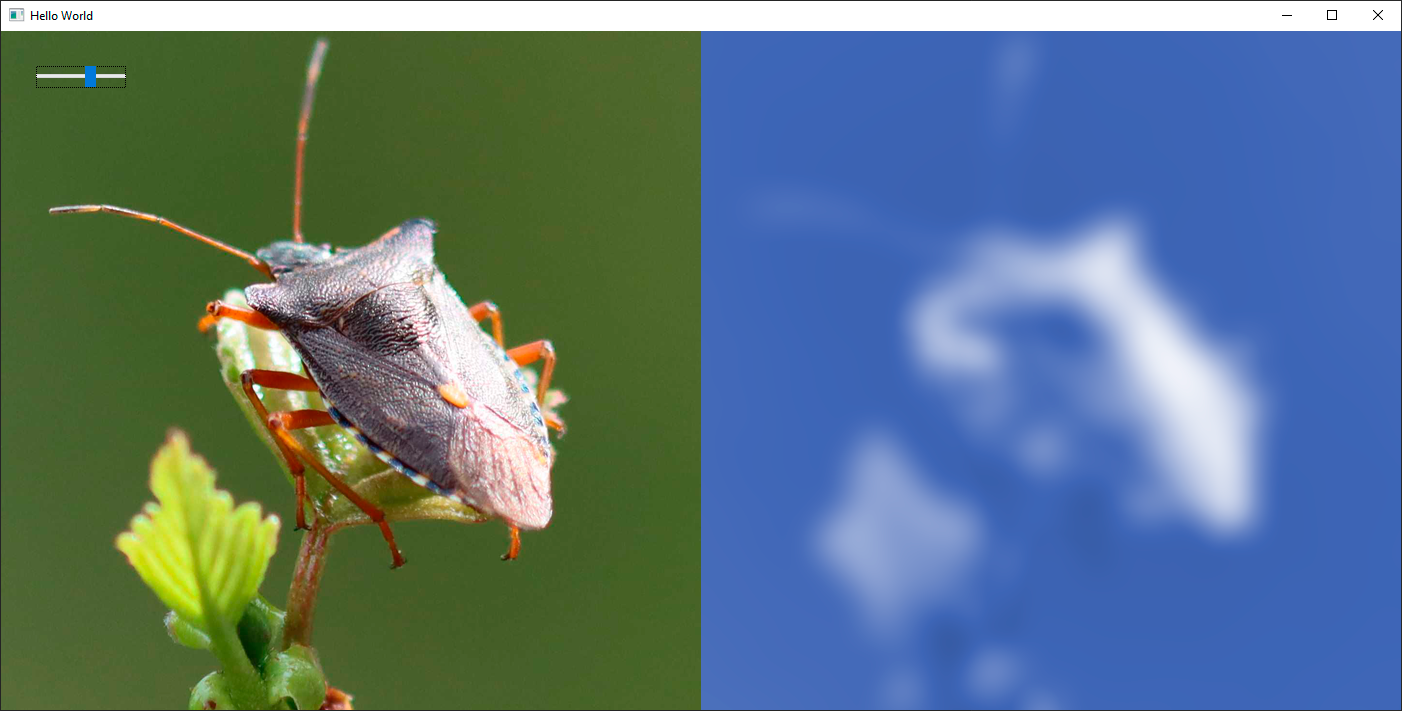
In this extension of the previous code, we have added some additional uniform parameters to the uniform buffer, specifying the destination color as hue, saturation and lightness. There's also a few extra helper functions, for converting between RGB and HSL. At the end of the main() function, the actual magic happens: Instead of just outputting the blurred RGB color directly, we extract its lightness. We then combine this with the input HSL color to produce the output.
In the example project, I have also added a slider which attaches to the hue, so you can easily cycle through different colors.
Conclusion
Hopefully this blog has inspired some of you to try writing your own custom shaders. Once you get past the initial learning curve, it is actually quite efficient to prototype and play around with new effects.
We will of course continue to provide as much convenience and assistance as we can in Qt. In the future, you can expect this to be even simpler and more approachable. But even today, it's quite possible to get whatever is in your head onto the screen with a very few lines of code.
Update 2022-09-12: The shader code in this blog previously did not compile with the OpenGL backend for RHI. This has been fixed in both the example projects and the source code presented here.


